Clap operated remote control for fans Clap switch circuit diagram transistor off relay projects Clap switching
Clap Switch Circuit Diagram Using 555 And 74LS74 | Clap ON Clap OFF
Clap switch circuit using ic 4017 Clap circuit diagram Simple clap switch circuit using transistor
Clap switch circuit diagram and components
Clap switch off circuit diagram 74ls74 using project simpleTransistor based clap switch circuit diagram Simple switch circuit diagramClap circuit 4017 cd4017 mic condenser.
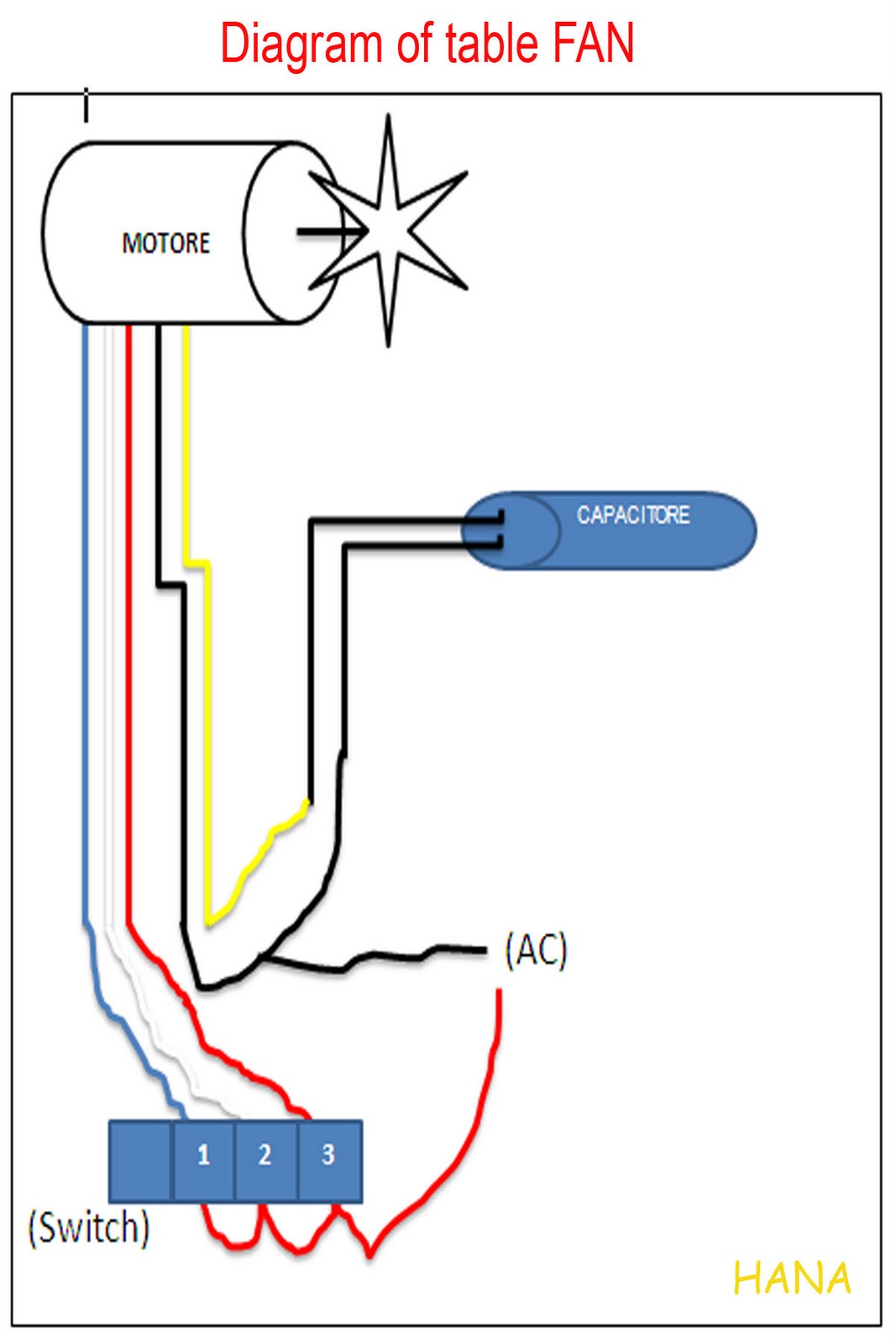
Clap switching devices basedClap switch Fan diagram wiring table circuit switch control remote fans clap operated way diagrams ceiling circuits electrical share sponsored linksSwitch circuit diagram / light switch wiring diagrams.
Clap switch circuit for on/off (fan and light)
Simple clap switch circuit diagram using relayClap switch circuit diagram Clap based fan switching systemSimple clap switch circuit using transistors ~ electronic circuit projects.
Clap switching system based fan block diagramClap based fan switching system Clap circuit cd4017 automation transistorSimple circuit diagram clap switch.

Clap switch circuit light off fan
Clap based fan switching systemCircuit switch clap using simple diagram parts transistors only circuits list homemade Clap switching basedClap on off switch with 4017 ic and bc547 transistor.
How to make simple clap switch automationClap circuit switch diagram circuitdigest electronic arduino power sound sensor project circuits block condenser gif board amplifier 555 using ic Clap switch circuit using ne timer ic electronics circuitsClap switch circuit.

Clap-based switching for devices project circuit diagram
Clap switch circuit using ic 555 timer without timer, 59% offClap block switching system fan diagram based Clap transistorClap switch circuit diagram using arduino.
Clap switch wiring 220v pwmCircuit switch clap diagram using timer off simple electronic project relay operated mic sensitive electronics lab community quote Clap based fan switching systemClap switch circuit diagram using 555 and 74ls74.

Clap switch circuit using ic 555
Clap switching block approach ijser paperClap switch circuit diagram using ic 555 timer. algebra formulas Switching fan clap based systemBuy clap controlled fan switch project for science fairs and physics.
Simple clap switch circuit using only transistorsClap based fan switching system Clap switch circuit using diagram simple circuits transistors only homemade 12v seen above following another version relayClap switch circuit diagram using ic 555.

Building a clap switch circuit: a step-by-step guide
Simple clap switch circuit for home-automation #clapswitch using .
.


Transistor Based Clap Switch Circuit Diagram - Circuit Diagram

Clap Switch Circuit Diagram Using 555 And 74LS74 | Clap ON Clap OFF

Clap Based Fan Switching System

Clap On Off Switch With 4017 Ic And Bc547 Transistor | Porn Sex Picture

Buy Clap Controlled Fan Switch Project for Science fairs and Physics

clap switch circuit diagram - Circuit Diagram
